Purpose of the Traceroute Tool
- This tool shows the route packets take to a target device from your computer. It is a connectivity and protocol latency testing tool.
- Retrieval of AS (autonomous system) numbers from IRR databases. Double click on a hop in a completed trace and the tool will query an IRR server for the AS number.
- Shows the Country that is allocated or assigned to each IPv4 address appearing in each hop.
About the Traceroute Tool
The Traceroute tool is an enhanced version of the classic network troubleshooting tool used to show the route packets take to a target device over an IP network. The target device can be on a local area network or across the internet.
Our enhanced version of traceroute supports both Windows style ICMP Echo Request and Unix style UDP methods. Advanced traceroute includes firewall penetrating TCP Traceroute and UDP fixed port traceroute. All methods depend on returning ICMP packets from intermediate devices along the route.
Our traceroute tool is fast. For example, an ICMP traceroute to netscantools.com takes 4 seconds including resolution of all IP addresses to hostnames. Statistics include packet loss, minimum, average and maximum round-trip time.
Here are the supported modes of Traceroute:
- ICMP Echo Request/Reply Traceroute IPv4 packets (similar to Windows command line tracert)
- UDP packet to unused port/ICMP port unreachable reply (similar to Unix/Linux classic traceroute methodology in that is uses variable ports)
- UDP Fixed Port where all the packets are sent to a fixed port.
- TCP packet to a used or unused port/TCP packet reply (RST, ACK, etc.)
- ICMPv6 Traceroute to IPv6 devices or websites such as ipv6.google.com
Related Tool Links
Traceroute Tool
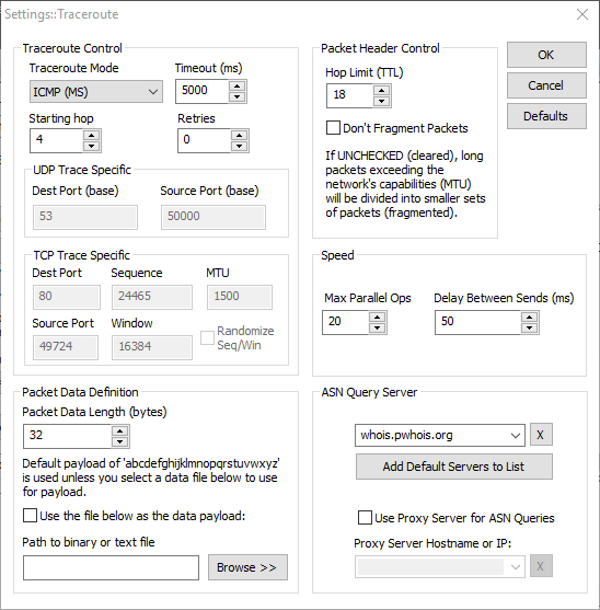
Traceroute Settings
ICMP Traceroute (IPv4 and IPv6) Modes
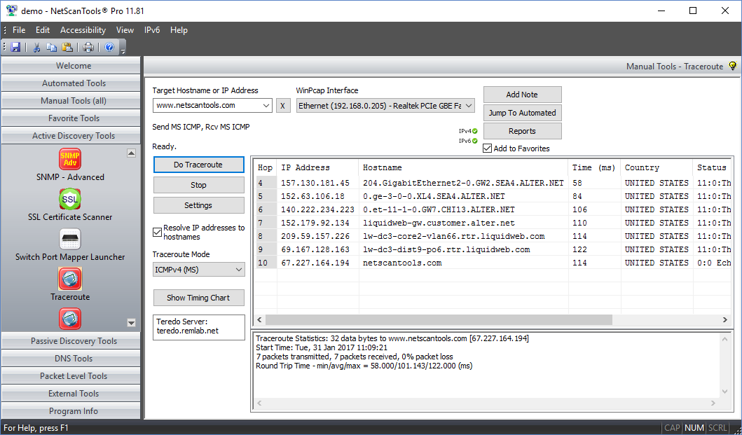
ICMP Traceroute modes use ICMP echo request packets to trace to a target. The target typically responds with ICMP echo reply packets. The intermediate hops reply with an ICMP type 11 time exceeded packet. The time it takes for a packet to get each hop/target and back is called the round trip time or latency.
NetScanTools Pro has two modes of ICMP ping (IPv4)
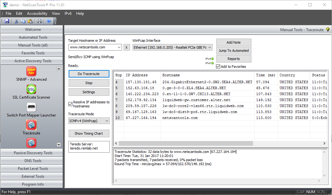
MS ICMP mode uses the operating system to send and receive the ping packets while the WinPcap mode of ICMP ping uses WinPcap as for both transmission and reception. The WinPcap method allows sub-millisecond timing resolution for ping round trip times while the MSICMP Ping method that has a resolution of milliseconds. Both modes send packets to each hop in parallel.
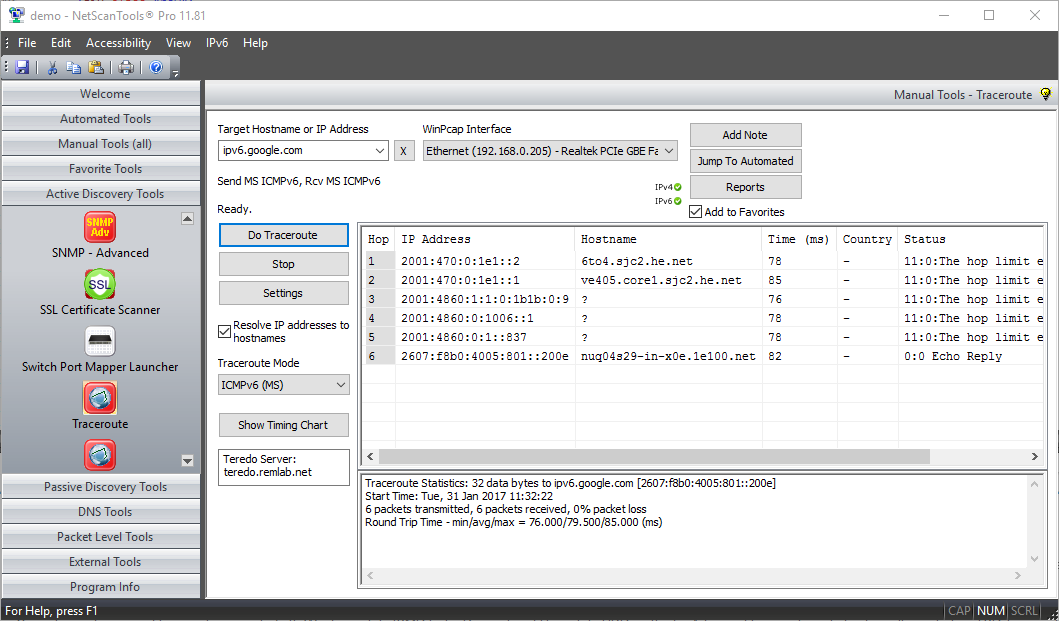
ICMPv6 Traceroute Mode
ICMPv6 Traceroute mode uses ICMPv6 echo request packets to trace to a target. The target typically responds with ICMPv6 echo reply packets. The intermediate hops reply with an ICMPv6 time exceeded packet. NetScanTools Pro has one mode of ICMPv6 ping: MS ICMPv6 mode uses an operating system function to send and receive the ping packets.
- The data portion of the payload for ICMP ping may be a simple 'a-z' repeating character string or the contents of any file you choose (binary or ascii).
ICMP packets are sometimes blocked by firewalls either between you and the target or on the target itself. We have two other methods of tracing the route to a target that may be more effective: UDP and TCP.
MSICMPv4 Mode

MSICMPv6 Mode
WinPcap ICMPv4 Mode
UDP Traceroute Modes (IPv4 only)
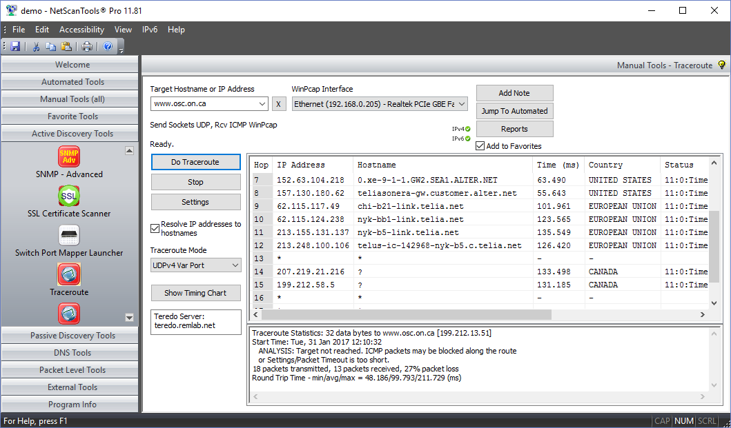
UDP Traceroute Modes use UDP packets to trace to a target. The target typically responds with ICMP port unreachable packets if you target a port that is customarily unused. The intermediate hops reply with an ICMP type 11 time exceeded packet. The time it takes for a packet to get the hop/target and back is called the round trip time or latency.
NetScanTools Pro has two modes of UDP traceroute: UDP Variable mode sends UDP packets to a linear set of UDP ports in parallel. The second mode sends the UDP packets to only one UDP port and waits for each responding ICMP packet - we recommend port 53 because it is the DNS port and is unprotected by firewalls. Both modes use WinPcap so you will see sub-millisecond timing resolution.
- The data portion of the payload for UDP packet may be a simple 'a-z' repeating character string or the contents of any file you choose (binary or ascii).
- UDP source and destination ports are user-defined.
UDP Variable Mode
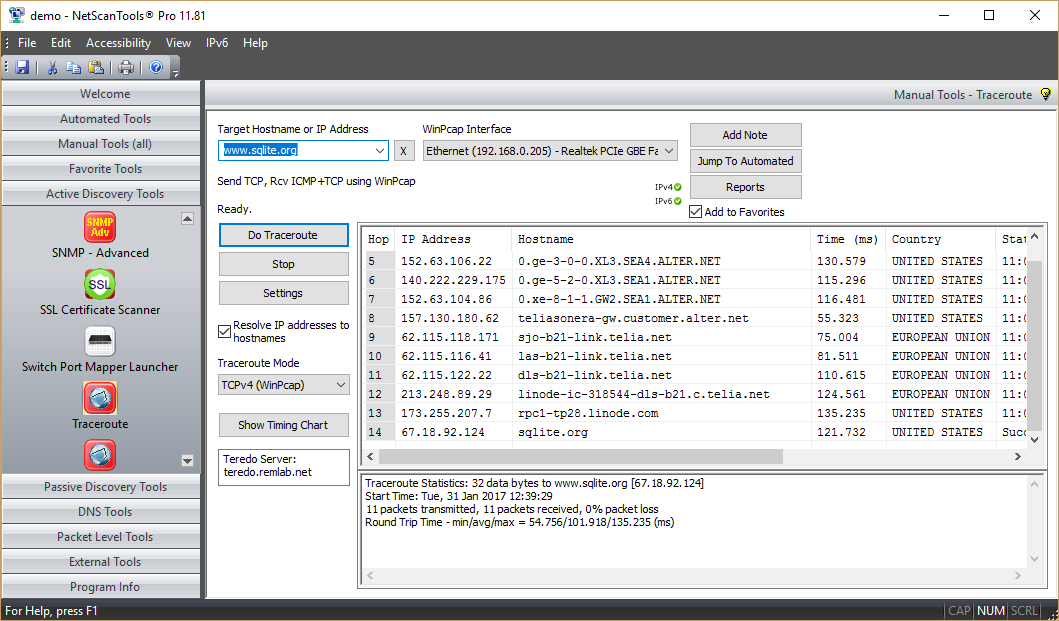
TCP Traceroute Mode (IPv4 only)
TCP Traceroute uses TCP SYN packets to trace to a target. The target typically responds with either TCP SYN/ACK or RST packets. The time it takes for a packet to get the target and back is the round trip time or latency. TCP traceroute uses WinPcap to send the TCP packets and receive the responding TCP packets. This mode allows you to see sub-millisecond timing resolution for TCP traceroute. You can use this tool to determine the latency for web servers or mail servers or just about any TCP service that is present on the target.
- TCP Traceroute uses either TCP SYN or ACK packets to elicit a responding TCP packet from the target. ICMP packets are not sent. The round-trip time of the packet pair is the latency of the TCP connection.
- TCP source and destination ports are separately user-defined.
- TCP header fields are user defined and may also be randomly selected. These fields are Sequence, Window, and Acknowledgement.
- TCP packet options section for MTU is included and the value is user defined.
- TCP Ping (WinPcap modes) allow full control over the Differentiated Services CodePoint Bits (DSCP) and the Explicit Congestion Notification bits, ECN-ECT, ECN-CE. You can change these bits to observe the effect on packet delivery through routers.
Traceroute sends TCP packets to a user specified port (web server port 80 is recommended). TCP Traceroute will often work through firewalls protecting the target where the other types of traceroute will not, however, no trace modes are guaranteed and depend on the target system configuration.
TCP Traceroute Mode
Timing Chart 1: Hops vs. Response Time
Traceroute Showing Linear Trend Line Analysis
This chart shows a traceroute to a web site. The chart shows a plot of hop number vs. the response time in milliseconds. The trend line is linear and is plotted as a red line. You can optionally see the formula in the format y = mx + b on the chart. You can export this image as bitmap (bmp) or portable network graphics (png) file. You can also copy the chart to the clipboard or print it in color.

Timing Chart 2: Hops vs. Response Time
Traceroute Showing 5th Degree Polynomial Trend Line Analysis
This is the same trace results but instead of a linear trend line fitting, it is using a 5th degree polynomial fitting. The chart shows the formula as y = aX^5 + bX^5 + cX^3 + dX^2 +eX + f. There are other polynomial fittings that you can select.

Video showing ICMPv6 Traceroute through a Teredo Tunnel
Video showing TCP Traceroute to a Web Server
Try the NetScanTools Pro demo free for 30 days
DEMO Version End User License Agreement (EULA)How to Uninstall
![]()
NetScanTools is a registered trademark of Northwest Performance Software, Inc.
'NetScanTools Pro', 'NetScanTools Standard', 'ipPulse', 'Northwest Performance Software' and 'NetScanTools.com', are trademarks of Northwest Performance Software, Inc.
Any trademarked names mentioned herein are the property of their respective owners.
About Us
Email Us
Call Us
Help & Support Center
NetScanTools® Pro Topics
© 2024 Northwest Performance Software, Inc. All Rights Reserved. | Privacy Policy